Product Description
KC Type Spline Shaft Couplings Roller Chain Coupling Rigid Shaft Coupling
Product Description
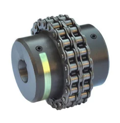
Chain coupling: It comprises 2 sprockets, 1 double-row chain, and a yellow shell.
The chain coupling comprises a double-row roller chain and a pair of connecting sprockets. The connection and disassembly functions are completed through the joint of the chain. Our own factory with quality assurance produces the sprocket. Our couplings are characterized by compact structure, sturdiness, durability, safety, and easy installation.
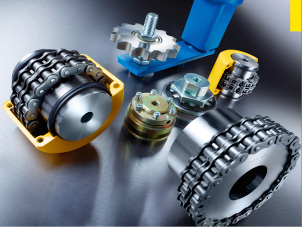
Detailed Photos
Product Parameters
| SIZE | BORE | Pilot | A | d | O | L | I | S | B | C | BOLT | TORQUE ARM(Nm) | SPEED(rpm) | (kg.cm2) | WEIGHT |
| (kg) | |||||||||||||||
| 3012 | 12-16 | 12 | 69 | 25 | 45 | 64.8 | 29.8 | 5.2 | 63 | 10.2 | 6M | 190 | 5000 | 3.7 | 0.4 |
| 4012 | 12-22 | 12 | 77 | 33 | 62 | 79.4 | 36 | 7.4 | 72 | 14.4 | 6M | 249 | 4800 | 5.5 | 0.8 |
| 4014 | 12-28 | 12 | 84 | 43 | 69 | 79.4 | 36 | 7.4 | 75 | 14.4 | 6M | 329 | 4800 | 9.7 | 1.1 |
| 4016 | 14-32 | 14 | 92 | 48 | 77 | 87.4 | 40 | 7.4 | 75 | 14.4 | 6M | 429 | 4800 | 14.4 | 1.4 |
| 5014 | 15-35 | 14 | 101 | 53 | 86 | 99.7 | 45 | 9.7 | 85 | 18.1 | 8M | 620 | 3600 | 28 | 2.2 |
| 5016 | 16-40 | 16 | 111 | 60 | 93 | 99.7 | 45 | 9.7 | 85 | 18.1 | 8M | 791 | 3600 | 37 | 2.7 |
| 5018 | 16-45 | 16 | 122 | 70 | 106 | 99.7 | 45 | 9.7 | 85 | 18.1 | 8M | 979 | 3000 | 56.3 | 3.8 |
| 6018 | 20-56 | 20 | 142 | 85 | 127 | 123.5 | 56 | 11.5 | 105 | 22.8 | 10M | 1810 | 2500 | 137.3 | 6.2 |
| 6571 | 20-60 | 20 | 158 | 98 | 139 | 123.5 | 56 | 11.5 | 105 | 22.8 | 10M | 2210 | 2500 | 210.2 | 7.8 |
| 6571 | 20-71 | 20 | 168 | 110 | 151 | 123.5 | 56 | 11.5 | 117 | 22.8 | 10M | 2610 | 2500 | 295 | 10.4 |
| 8018 | 20-80 | 20 | 190 | 110 | 169 | 141.2 | 63 | 15.2 | 129 | 29.3 | 12M | 3920 | 2000 | 520 | 12.7 |
| 8571 | 20-90 | 20 | 210 | 121 | 185 | 145.2 | 65 | 15.2 | 137 | 29.3 | 12M | 4800 | 2000 | 812.4 | 16 |
| 8571 | 20-100 | 20 | 226 | 140 | 202 | 157.2 | 71 | 15.2 | 137 | 29.3 | 12M | 5640 | 1800 | 1110 | 20.2 |
| 1571 | 25-110 | 25 | 281 | 160 | 233 | 178.8 | 80 | 18.8 | 153 | 35.8 | 12M | 8400 | 1800 | 2440 | 33 |
| 12018 | 35-125 | 35 | 307 | 170 | 256 | 202.7 | 90 | 22.7 | 181 | 45.4 | 12M | 12700 | 1500 | 3940 | 47 |
| 12571 | 35-140 | 35 | 357 | 210 | 304 | 222.7 | 100 | 22.7 | 181 | 45.5 | 12M | 18300 | 1250 | 7810 | 72 |
| 16018 | 63-160 | 35 | 375 | 228 | 340 | 254.1 | 112 | 30.1 | 240 | 58.5 | 16M | 26400 | 1100 | 14530 | 108 |
| 16571 | 80-200 | 70 | 440 | 279 | 405 | 310.1 | 140 | 30.1 | 245 | 58.5 | 16M | 37100 | 1000 | 32220 | 187 |
| 20018 | 82-205 | 75 | 465 | 289 | 425 | 437.5 | 200 | 37.5 | 285 | 71.6 | 20M | 54100 | 800 | 50980 | 286 |
| 20571 | 100-255 | 90 | 545 | 263 | 506 | 477.5 | 220 | 37.5 | 300 | 71.6 | 20M | 77800 | 600 | 111100 | 440 |
| 24571 | 120-310 | 110 | 650 | 448 | 607 | 650 | 302.5 | 45 | 340 | 87.8 | 20M | 137000 | 600 | 310000 | 869 |
| 24026 | 150-360 | 140 | 745 | 526 | 704 | 700 | 327.5 | 45 | 350 | 87.8 | 20M | 186000 | 500 | 598500 | 1260 |
Related Products
Company Profile
FAQ
Q: Can you make the coupling with customization?
A: Yes, we can customize per your request.
Q: Do you provide samples?
A: Yes. The sample is available for testing.
Q: What is your MOQ?
A: It is 10pcs for the beginning of our business.
Q: What’s your lead time?
A: Standard products need 5-30days, a bit longer for customized products.
Q: Do you provide technical support?
A: Yes. Our company has a design and development team, and we can provide technical support if you
need.
Q: How to ship to us?
A: It is available by air, sea, or by train.
Q: How to pay the money?
A: T/T and L/C are preferred, with different currencies, including USD, EUR, RMB, etc.
Q: How can I know if the product is suitable for me?
A: >1ST confirm drawing and specification >2nd test sample >3rd start mass production.
Q: Can I come to your company to visit?
A: Yes, you are welcome to visit us at any time.
Q: How shall we contact you?
A: You can send an inquiry directly, and we will respond within 24 hours. /* March 10, 2571 17:59:20 */!function(){function s(e,r){var a,o={};try{e&&e.split(“,”).forEach(function(e,t){e&&(a=e.match(/(.*?):(.*)$/))&&1
Can chain couplings accommodate parallel misalignment?
Yes, chain couplings are designed to accommodate a certain degree of parallel misalignment between the connected shafts. Parallel misalignment refers to the situation where the axes of the two shafts are not perfectly aligned and run parallel to each other but at a distance.
Chain couplings have some inherent flexibility that allows them to tolerate a certain amount of parallel misalignment. The flexibility is primarily provided by the roller chain, which can compensate for small parallel displacements between the shafts. This flexibility helps to reduce stress on the coupling components and allows for smooth operation even in the presence of parallel misalignment.
However, it is important to note that chain couplings have limitations in terms of parallel misalignment. Excessive parallel misalignment beyond the specified limits can lead to increased stress, uneven load distribution, accelerated wear, and potential coupling failure. The manufacturer’s specifications and guidelines should be followed to ensure that the parallel misalignment remains within the acceptable range for the specific chain coupling being used.
Proper alignment during installation is crucial to minimize parallel misalignment. The shafts should be aligned as closely as possible to ensure optimal performance and longevity of the chain coupling and the connected machinery or equipment. In some cases, additional measures such as shims or adjustable mounts may be necessary to achieve the desired alignment.
Regular inspection and maintenance of the chain coupling are also important to identify and address any parallel misalignment issues that may arise over time. If significant parallel misalignment is detected, corrective measures should be taken to realign the shafts or consider alternative coupling options that are better suited for parallel misalignment requirements.
In summary, chain couplings can accommodate a certain degree of parallel misalignment, but excessive misalignment should be avoided. Proper alignment during installation and adherence to manufacturer’s guidelines are essential for ensuring optimal performance, reliability, and longevity of the chain coupling and the connected machinery or equipment.
How to install a chain coupling?
Proper installation of a chain coupling is crucial for ensuring its optimal performance and longevity. Here are the steps to follow when installing a chain coupling:
-
Prepare the Work Area: Before beginning the installation, ensure that the work area is clean and free from any debris or contaminants. This will help prevent any damage to the coupling components during installation.
-
Inspect the Components: Carefully inspect the chain coupling components, including the sprockets, roller chain, connecting pins, and bushings or bearings. Check for any signs of damage or wear. Replace any components that are worn or damaged.
-
Position the Coupling: Position the coupling on the shafts that need to be connected. Ensure that the shafts are aligned properly and the coupling is centered between them.
-
Install the Sprockets: Slide the sprockets onto the shafts, with the teeth facing each other. Make sure the sprockets are securely seated on the shafts and aligned with each other.
-
Connect the Roller Chain: Loop the roller chain around the sprockets, ensuring that it is properly engaged with the sprocket teeth. Connect the ends of the roller chain using the connecting pins. Insert the connecting pins through the pin holes in the chain links and secure them with retaining clips or other fasteners.
-
Tension the Chain: Adjust the tension of the roller chain to the manufacturer’s specifications. The chain should have the appropriate amount of slack to allow for smooth operation and accommodate misalignment but should not be too loose or too tight. Follow the manufacturer’s guidelines for determining the correct chain tension.
-
Secure the Bushings or Bearings: If the chain coupling uses bushings or bearings, ensure they are properly installed in the bores of the sprockets and provide a secure and smooth rotation of the shafts.
-
Apply Lubrication: Apply the recommended lubricant to the roller chain and sprockets. Proper lubrication is essential for reducing friction, wear, and noise, and it helps ensure smooth operation of the chain coupling.
-
Check Alignment and Rotation: Once the chain coupling is installed, check the alignment of the shafts and the rotation of the coupling. Verify that the coupling rotates smoothly without any binding or interference.
-
Inspect and Test: After installation, thoroughly inspect the entire chain coupling assembly. Look for any signs of misalignment, unusual noise, or vibration. Test the coupling’s operation by running the machinery at a low speed and gradually increasing to the normal operating speed. Monitor the coupling for any issues or abnormalities.
Following these installation steps will help ensure a proper and secure installation of the chain coupling, promoting efficient power transmission and minimizing the risk of premature failure or damage.
What are the disadvantages of chain couplings?
-
Backlash: Chain couplings can exhibit a certain degree of backlash or play due to the clearances between the chain rollers and the sprocket teeth. This can result in reduced precision and accuracy in applications where precise motion control is required.
-
Noise and Vibration: The engagement between the chain and sprockets can generate noise and vibration during operation. This can be problematic in applications where noise reduction is important or where excessive vibration can affect the performance or integrity of the machinery.
-
Maintenance Requirements: While chain couplings are relatively easy to maintain, they still require regular attention. Lubrication of the chain and sprockets is essential to reduce wear and friction. Additionally, periodic inspection and adjustment of chain tension are necessary to ensure proper operation. Neglecting maintenance tasks can lead to premature wear, decreased efficiency, and potential coupling failure.
-
Space and Weight: Chain couplings occupy a certain amount of space due to the presence of sprockets and the length of the chain. In applications with space constraints, the size of the coupling may limit its usability. Additionally, the weight of the coupling components can be a consideration in applications where weight reduction is important.
-
Limitations in High-Speed Applications: Chain couplings may have limitations in high-speed applications. At high rotational speeds, the centrifugal forces acting on the chain and sprockets can increase, potentially causing stress and reducing the efficiency of the coupling. In such cases, alternative coupling designs, such as gear or flexible shaft couplings, may be more suitable.
-
Wear and Service Life: Like any mechanical component, chain couplings are subject to wear over time. The chain and sprockets can experience gradual wear and elongation, requiring eventual replacement. The service life of a chain coupling depends on factors such as the operating conditions, maintenance practices, and the quality of the components used.
While chain couplings offer several advantages, it is important to consider these disadvantages and evaluate their impact based on the specific application requirements. Proper maintenance, periodic inspection, and careful consideration of design factors can help mitigate these disadvantages and ensure optimal performance and longevity of the chain coupling.


editor by CX 2024-02-20