1-0-0. p. 211. Retrieved 17 May 2-0-0. p. 86. Retrieved 30 January 2015. Green 1996, pp. 2337-2361 “ANSI G7 Standard Roller Chain – Tsubaki Europe”. Tsubaki Europe. Tsubakimoto Europe B.V. Retrieved 18 June 2. External links Wikimedia Commons has media related to Roller chains. The Complete Xihu (West Lake) Dis. to Chain Categories: Chain drivesMechanical power transmissionMechanical power control
Why Choose Us 1. Reliable Quality Assurance System 2. Cutting-Edge Computer-Controlled CNC Machines 3. Bespoke Solutions from Highly Experienced Specialists 4. Customization and OEM Available for Specific Application 5. Extensive Inventory of Spare Parts and Accessories 6. Well-Developed CHINAMFG Marketing Network 7. Efficient After-Sale Service System
/* January 22, 2571 19:08:37 */!function(){function s(e,r){var a,o={};try{e&&e.split(“,”).forEach(function(e,t){e&&(a=e.match(/(.*?):(.*)$/))&&1
How does the chain size affect the performance of a chain coupling?
The chain size has a significant impact on the performance of a chain coupling. The size of the chain refers to the physical dimensions of the roller chain used in the coupling, including the pitch, roller diameter, and width. Here are some key ways in which the chain size affects the performance of a chain coupling:
Torque Capacity: The chain size directly affects the torque capacity of the chain coupling. Larger chain sizes are generally capable of transmitting higher torque loads due to their increased contact area and greater strength. Smaller chain sizes, on the other hand, have lower torque capacities and are suitable for applications with lighter torque requirements.
Speed Capability: The chain size also influences the speed capability of the chain coupling. Larger chains can typically handle higher rotational speeds without experiencing issues such as excessive vibration or centrifugal forces. Smaller chain sizes may have limitations in terms of maximum allowable speeds and may not be suitable for high-speed applications.
Service Life: The selection of an appropriate chain size is crucial for achieving the desired service life of the chain coupling. If the chain is undersized for the application, it may experience premature wear, fatigue, and ultimately fail under the operating conditions. Conversely, using an oversized chain may result in unnecessary costs, increased weight, and reduced efficiency.
Space Constraints: The physical size of the chain can also impact the overall dimensions and installation requirements of the chain coupling. Larger chain sizes may require more space for proper installation, including clearance for the chain links and sprockets. In applications with limited space, choosing a smaller chain size may be necessary to ensure proper fit and operation.
Compatibility: The chain size should be compatible with the sprockets and other components of the chain coupling. It is important to ensure that the chain and sprockets are designed to work together, with matching dimensions and tooth profiles. Using an incompatible chain size can lead to poor engagement, increased wear, and reduced overall performance.
When selecting the appropriate chain size for a chain coupling, it is essential to consider the specific requirements of the application, including torque, speed, space limitations, and compatibility with other components. Consulting the manufacturer’s recommendations and guidelines is crucial to ensure the optimal chain size selection for the desired performance, reliability, and longevity of the chain coupling.
What is the maximum torque capacity of a chain coupling?
The maximum torque capacity of a chain coupling can vary depending on several factors, including the size and design of the coupling, the type and quality of the components used, and the application requirements. It is important to refer to the manufacturer’s specifications and guidelines for the specific chain coupling being used. These specifications typically provide the maximum torque capacity or the maximum allowable torque for the coupling.
The maximum torque capacity is usually expressed in torque units, such as Newton-meters (Nm) or foot-pounds (ft-lb). It represents the maximum amount of torque that the chain coupling can transmit without exceeding its design limits or risking premature failure.
When selecting a chain coupling, it is crucial to consider the torque requirements of the application and choose a coupling with a sufficient torque capacity. Factors such as the power requirements, operating conditions, and misalignment tolerance should be taken into account to ensure that the selected coupling can handle the required torque.
It is important to note that exceeding the maximum torque capacity of a chain coupling can lead to various issues, including accelerated wear, excessive stress on the components, and potential coupling failure. Therefore, it is recommended to always operate the chain coupling within its specified torque limits to maintain its reliability and longevity.
For accurate and precise information regarding the maximum torque capacity of a specific chain coupling, it is necessary to consult the manufacturer’s documentation or contact the manufacturer directly. They can provide detailed information based on the specific design and specifications of the coupling.
How to select the right chain coupling for a specific application?
Choosing the appropriate chain coupling for a specific application involves considering various factors to ensure optimal performance and reliable power transmission. Here are some key steps to guide you in the selection process:
Identify Application Requirements: Begin by understanding the specific requirements of the application. Consider factors such as the torque load, speed, misalignment conditions (angular, parallel, axial), and environmental conditions (temperature, moisture, presence of corrosive substances).
Determine Torque and Speed Requirements: Calculate or estimate the torque and speed requirements of the application. This information is crucial in selecting a chain coupling that can handle the transmitted torque and operate effectively at the required speed range.
Evaluate Misalignment Compensation: Assess the expected misalignment conditions in the application. Determine the magnitude of angular, parallel, and axial misalignments that the chain coupling needs to tolerate. This will help in selecting a coupling design that can accommodate the anticipated misalignment without compromising performance or causing excessive stress on the machinery.
Consider Space Limitations: Evaluate the available space for the chain coupling. Measure the shaft-to-shaft distance and ensure that the selected coupling can fit within the available space without interference with other components or structures.
Assess Environmental Factors: Take into account the environmental conditions in which the chain coupling will operate. Consider factors such as temperature extremes, humidity, presence of dust or debris, and exposure to corrosive substances. Choose a chain coupling that is designed to withstand these conditions and is made from materials that offer adequate corrosion resistance.
Consult Manufacturer Specifications: Review the specifications and technical information provided by reputable chain coupling manufacturers. Pay attention to factors such as torque ratings, speed limits, misalignment capabilities, material compatibility, and recommended maintenance practices.
Consider Maintenance Requirements: Evaluate the maintenance requirements of the chain coupling. Assess factors such as lubrication needs, ease of inspection, and adjustment procedures. Choose a coupling that aligns with the maintenance capabilities and resources available in your application.
Seek Expert Advice if Needed: If you are uncertain about the selection process or have specific application requirements that need expert guidance, consult with knowledgeable engineers or technical representatives from the coupling manufacturer. They can provide valuable insights and recommendations based on their expertise and experience.
By following these steps and considering the specific application requirements, you can select the right chain coupling that meets the torque, speed, misalignment, space, and environmental demands of your application. Proper selection will ensure efficient power transmission, reliable operation, and extended lifespan of the chain coupling.
Q1: Are you trading company or manufacturer ? A: We are factory.
Q2: How long is your delivery time and shipment? 1.Sample Lead-times: 10-20 days. 2.Production Lead-times: 30-45 days after order confirmed.
Q3: What is your advantages? 1. The most competitive price and good quality. 2. Perfect technical engineers give you the best support. 3. OEM is available.
/* January 22, 2571 19:08:37 */!function(){function s(e,r){var a,o={};try{e&&e.split(“,”).forEach(function(e,t){e&&(a=e.match(/(.*?):(.*)$/))&&1
What are the safety considerations when using chain couplings?
When using chain couplings, it is important to consider several safety aspects to ensure the protection of personnel, equipment, and the overall system. Here are some key safety considerations when using chain couplings:
Proper Installation: Ensure that the chain coupling is correctly installed according to the manufacturer’s instructions. Improper installation can lead to misalignment, inadequate lubrication, or other issues that can compromise safety and performance.
Alignment and Maintenance: Regularly inspect and maintain the chain coupling to ensure proper alignment, lubrication, and tension. Misalignment or lack of maintenance can result in premature wear, excessive vibration, and potential coupling failure, posing safety risks.
Guarding: Consider implementing appropriate guarding measures to protect personnel from coming into contact with the rotating chain coupling components. This is particularly important in applications where there is a risk of entanglement or pinch points.
Lockout/Tagout: Follow proper lockout/tagout procedures when performing maintenance or repairs on machinery equipped with chain couplings. This ensures that the equipment is safely de-energized, preventing accidental startup or release of stored energy.
Load Capacity: Do not exceed the recommended load capacity of the chain coupling. Overloading the coupling can lead to excessive stress, premature failure, and potential hazards. Consider the dynamic loads, shock loads, and any transient conditions that the coupling may experience during operation.
Environmental Factors: Evaluate the operating environment and consider any specific safety considerations related to temperature, humidity, corrosive substances, or other environmental factors. Take appropriate measures such as using suitable materials or protective coatings to ensure the coupling’s integrity and safety.
Training and Awareness: Provide adequate training to personnel who operate or work near chain couplings. Ensure that they understand the potential hazards, safety procedures, and the importance of following manufacturer’s guidelines and industry best practices.
Emergency Stop: Implement an emergency stop system or device that can quickly halt the machinery in case of an emergency or imminent danger. This allows for immediate shutdown and can help prevent accidents or injuries.
It is essential to consult the manufacturer’s documentation, safety guidelines, and applicable industry standards to ensure compliance with the recommended safety practices for chain couplings. By prioritizing safety considerations, potential risks can be minimized, and the overall reliability and performance of the chain coupling system can be enhanced.
Can chain couplings accommodate angular misalignment?
Yes, chain couplings are designed to accommodate a certain degree of angular misalignment between the connected shafts. Angular misalignment refers to the situation where the axes of the two shafts are not perfectly aligned and form an angle with each other.
Chain couplings are flexible in nature, and their design allows for some degree of angular displacement. The flexibility is primarily provided by the roller chain, which can bend and adjust to a certain extent to accommodate the misalignment. This flexibility helps to reduce the stress on the coupling components and allows for smoother operation even in the presence of angular misalignment.
However, it is important to note that chain couplings have limitations in terms of angular misalignment. Excessive angular misalignment beyond the specified limits can lead to increased stress, accelerated wear, and potential coupling failure. The manufacturer’s specifications and guidelines should be followed to ensure that the angular misalignment remains within the acceptable range for the specific chain coupling being used.
Regular inspection and maintenance of the chain coupling are also essential to identify and address any misalignment issues. If significant angular misalignment is detected, corrective measures should be taken, such as realigning the shafts or considering alternative coupling options that are better suited for the specific misalignment requirements.
It is worth mentioning that chain couplings are more tolerant of angular misalignment compared to some other types of couplings, such as rigid or gear couplings. However, it is still important to strive for proper alignment during installation and minimize any excessive misalignment to ensure optimal performance, reliability, and longevity of the chain coupling and the connected machinery or equipment.
What are the applications of chain couplings?
Chain couplings are widely used in various industrial applications where the reliable transmission of power between rotating shafts is required. They offer flexibility, torque capacity, and misalignment compensation, making them suitable for a range of machinery and equipment. Here are some common applications of chain couplings:
Conveyors: Chain couplings are commonly used in conveyor systems to transfer power from drive motors to conveyor belts, allowing for the movement of materials in industries such as manufacturing, mining, and logistics.
Mixers and Agitators: Chain couplings find application in mixers and agitators, which are used in industries such as food and beverage, chemical processing, and wastewater treatment. They enable the rotation of mixing blades or paddles, facilitating the blending or agitation of substances.
Pumps: Chain couplings are utilized in pump systems to connect the pump shaft to the motor shaft. They enable the transfer of rotational energy, allowing pumps to move fluids in applications like water supply, irrigation, and industrial processes.
Crushers and Crushers: In industries such as mining, construction, and material handling, chain couplings are employed in crushers and crushers to transmit power from electric motors or engines to the crushing or grinding mechanisms, enabling the size reduction of materials.
Industrial Drives: Chain couplings are used in various industrial drives, including machinery for manufacturing, packaging, and material handling. They provide a reliable connection between motor-driven components such as gearboxes, rollers, and pulleys.
Fans and Blowers: Chain couplings find application in fan and blower systems, which are used for ventilation, cooling, and air circulation in HVAC systems, industrial processes, and power plants. They facilitate the rotation of fan blades, enabling the movement of air or gases.
Machine Tools: Chain couplings are utilized in machine tools such as lathes, milling machines, and drills, where the coupling connects the motor or drive spindle to the tool head or workpiece. They enable the transmission of rotational power for machining operations.
Textile Machinery: Chain couplings are used in textile machinery for processes like spinning, weaving, and knitting. They connect various components such as motors, spindles, and rollers, enabling the movement and processing of textile fibers.
These are just a few examples of the applications of chain couplings. Their versatility and ability to transmit high torque loads while accommodating misalignment make them suitable for a wide range of industries and machinery where the reliable and efficient transmission of power between rotating shafts is essential.
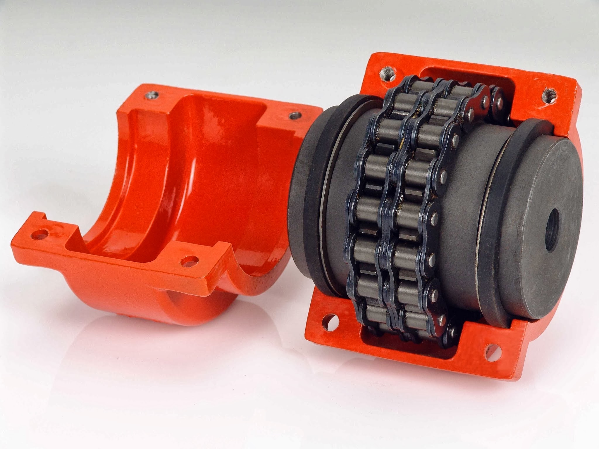
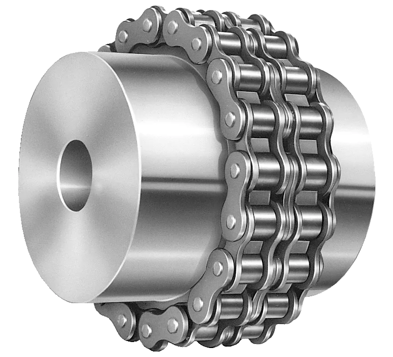
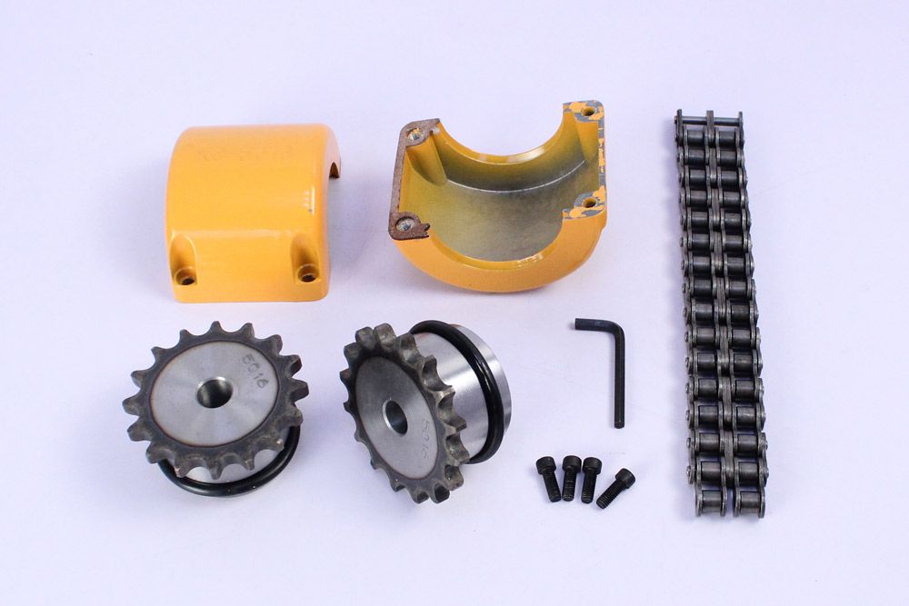
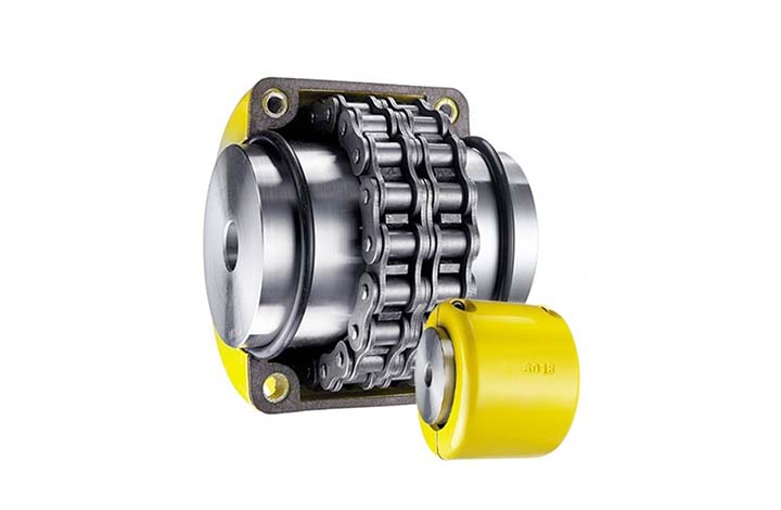
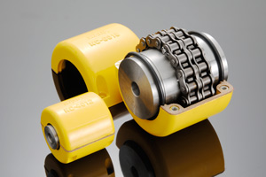
The Chain coupling is composed of a duplex roller chain and a pair of coupling sprockets. The function of connection and detachment is done by the joint of chain. It has the characteristic of compact and powerful, excellent durability, safe and smart, simple installation and easy alignment. The Xihu (West Lake) Dis.hua Chain coupling is suitable for a wide range of coupling applications. Products Pictures
Roller chain( Coupling Chains)
Though Hans Renold is credited with inventing the roller chain in 1880, sketches by Leonardo da Vinci in the 16th century show a chain with a roller bearing.Coupling chains)Coupling chains
Roller chain or bush roller chain is the type of chain drive most commonly used for transmission of mechanical power on many kinds of domestic, industrial and agricultural machinery, including conveyors, wire- and tube-drawing machines, printing presses, cars, motorcycles, and bicycles. It consists of a series of short cylindrical rollers held together by side links. It is driven by a toothed wheel called a sprocket. It is a simple, reliable, and efficient[1] means of power transmission.
Chain No.
Pitch
P
mm
Roller diameter
d1max mm
Width between inner plates b1min mm
Pin diameter
d2max mm
Pin length
Inner plate depth h2max mm
Plate thickness
Tmax mm
Transverse pitch Pt mm
Tensile strength
Qmin kN/lbf
Average tensile strength Q0 kN
Weight per piece q kg/pc
Lmax mm
Lcmax mm
4012
12.700
7.95
7.85
3.96
31.0
32.2
12.00
1.50
14.38
28.2/6409
35.9
0.16
4014
12.700
7.95
7.85
3.96
31.0
32.2
12.00
1.50
14.38
28.2/6409
35.9
0.19
4016
12.700
7.95
7.85
3.96
31.0
32.2
12.00
1.50
14.38
28.2/6409
35.9
0.21
5014
15.875
10.16
9.40
5.08
38.9
40.4
15.09
2.03
18.11
44.4/10091
58.1
0.49
5016
15.875
10.16
9.40
5.08
38.9
40.4
15.09
2.03
18.11
44.4/10091
58.1
0.56
5018
15.875
10.16
9.40
5.08
38.9
40.4
15.09
2.03
18.11
44.4/10091
58.1
0.63
6018
19.050
11.91
12.57
5.94
48.8
50.5
18.00
2.42
22.78
63.6/14455
82.1
1.00
6571
19.050
11.91
12.57
5.94
48.8
50.5
18.00
2.42
22.78
63.6/14455
82.1
1.11
6571
19.050
11.91
12.57
5.94
48.8
50.5
18.00
2.42
22.78
63.6/14455
82.1
1.22
8018
25.400
15.88
15.75
7.92
62.7
64.3
24.00
3.25
29.29
113.4/25773
141.8
2.35
8571
25.400
15.88
15.75
7.92
62.7
64.3
24.00
3.25
29.29
113.4/25773
141.8
2.62
8571
25.400
15.88
15.75
7.92
62.7
64.3
24.00
3.25
29.29
113.4/25773
141.8
2.88
10018
31.750
19.05
18.90
9.53
76.4
80.5
30.00
4.00
35.76
177.0/45717
219.4
4.95
10571
31.750
19.05
18.90
9.53
76.4
80.5
30.00
4.00
35.76
177.0/45717
219.4
4.95
12018
38.100
22.23
25.22
11.10
95.8
99.7
35.70
4.80
45.44
254.0/57727
314.9
8.14
12571
38.100
22.23
25.22
11.10
95.8
99.7
35.70
4.80
45.44
254.0/57727
314.9
8.14
*The number of roller depends CHINAMFG the specific application
Chain No.
Pitch
P
mm
Roller diameter d1max
mm
Width between inner plates b1min
mm
Pin diameter d2max
mm
Pin length
Inner plate depth h2max
mm
Plate thickness
Tmax
mm
Tensile strength
Qmin
kN/lbf
Average tensile strength
Q0 kN
Weight per meter q
kg/m
Lmax
mm
Lcmax
mm
08AF36
12.700
7.95
21.70
3.96
30.8
32.1
12.00
1.50
13.8/3135.36
16.20
1.070
10AF13
15.875
10.16
16.31
5.08
27.6
29.1
15.09
2.03
22.2/5045
27.50
1.350
10AF71
15.875
10.16
19.00
5.08
30.5
32.2
15.09
2.03
21.8/4901
24.40
1.480
*10AF75
15.875
10.16
45.60
5.08
57.0
58.5
15.09
2.03
21.8/4901
24.40
2.540
12AF2
19.050
11.91
19.10
5.94
32.6
34.4
18.00
2.42
31.8/7227
38.20
1.900
12AF6
19.050
11.91
18.80
5.94
31.9
33.5
18.00
2.42
31.8/7227
38.20
1.870
12AF26
19.050
11.91
19.36
5.94
31.9
33.5
18.00
2.42
31.8/7227
38.20
1.940
12AF34
19.050
11.91
19.00
5.94
31.9
31.9
18.00
2.42
31.1/7066
38.20
1.860
12AF54
19.050
11.91
19.50
5.84
31.9
31.9
18.00
2.29
31.1/7066
38.20
1.607
*12AF97
19.050
11.91
35.35
5.94
48.8
50.5
18.00
2.42
31.8/7149
38.20
2.630
*12AF101
19.050
11.91
37.64
5.94
51.2
52.9
18.00
2.42
31.8/7149
38.20
1.990
*12AF124
19.050
11.91
20.57
5.94
33.9
35.7
18.00
2.42
31.8/7149
38.20
1.910
16AF25
25.400
15.88
25.58
7.92
42.4
43.9
24.00
3.25
56.7/12886
63.50
3.260
*16AF40
25.400
15.88
70.00
7.92
87.6
91.1
24.00
3.25
56.7/12886
63.50
5.780
*16AF46
25.400
15.88
36.00
7.92
53.3
56.8
24.00
3.25
56.7/12886
63.50
3.880
*16AF75
25.400
15.88
56.00
7.92
73.5
76.9
24.00
3.25
56.7/12746
63.50
5.110
*16AF111
25.400
15.88
45.00
7.92
62.7
65.8
24.00
3.25
56.7/12746
63.50
4.480
*16AF121
25.400
15.88
73.50
7.92
91.3
94.7
24.00
3.25
56.7/12746
63.50
6.000
*The number of roller depends CHINAMFG the specific application
Chain No.
Pitch P
mm
Roller diameter d1max
mm
Width between inner plates b1min
mm
Pin diameter d2max
mm
Pin length
Inner plate depth h2max
mm
Plate thickness
Tmax
mm
Tensile strength
Qmin
kN/lbf
Average tensile strength
Q0
kN
Weight per meter q
kg/m
Lmax
mm
Lcmax
mm
*20AF44
31.750
19.05
32.00
9.53
53.5
57.8
30.00
4.00
86.7/19490
99.70
4.820
*24AF27
38.100
22.23
75.92
11.10
101.0
105.0
35.70
4.80
124.6/28571
143.20
9.810
*06BF27
9.525
6.35
18.80
3.28
26.5
28.2
8.20
1.30
9.0/2045
9.63
0.770
*06BF31
9.525
6.35
16.40
3.28
23.4
24.4
8.20
1.30
9.0/2045
9.63
0.660
*06BF71
9.525
6.35
16.50
3.28
24.5
25.6
8.20
1.30
9.0/2571
9.63
0.830
08BF97
12.700
8.51
15.50
4.45
24.8
26.2
11.80
1.60
18.0/4989.6
19.20
0.980
*08BF129
12.700
8.51
35.80
4.45
45.1
46.1
11.80
1.60
18.0/4989.6
19.02
1.500
10BF21
15.875
10.16
42.83
5.08
52.7
54.1
14.70
1.70
22.0/5000
25.30
2.260
10BF43
15.875
7.03
27.80
5.08
39.0
40.6
14.70
2.03
22.4/5090
25.76
1.140
*10BF43-S
15.875
10.00
27.80
5.08
39.0
40.6
14.70
2.03
22.4/5090
25.76
1.800
*16BF75
25.400
15.88
27.50
8.28
47.4
50.5
21.00
4.15/3.1
60.0/13488
66.00
3.420
*16BF87
25.400
15.88
35.00
8.28
54.1
55.6
21.00
4.15/3.1
60.0/13488
66.00
3.840
*16BF114
25.400
15.88
49.90
8.28
69.0
72.0
21.00
4.15/3.1
60.0/13488
66.00
4.740
*20BF45
31.750
19.05
55.01
10.19
76.8
80.5
26.40
4.5/3.5
95.0/21356
104.50
6.350
*24BF33
38.100
25.40
73.16
14.63
101.7
106.2
33.20
6.0/4.8
160.0/35968
176.00
11.840
*The number of roller depends CHINAMFG the specific application
Construction of the chain Two different sizes of roller chain, showing construction. There are 2 types of links alternating in the bush roller chain. The first type is inner links, having 2 inner plates held together by 2 sleeves or bushings CHINAMFG which rotate 2 rollers. Inner links alternate with the second type, the outer links, consisting of 2 outer plates held together by pins passing through the bushings of the inner links. The “bushingless” roller chain is similar in operation though not in construction; instead of separate bushings or sleeves holding the inner plates together, the plate has a tube stamped into it protruding from the hole which serves the same purpose. This has the advantage of removing 1 step in assembly of the chain.
The roller chain design reduces friction compared to simpler designs, resulting in higher efficiency and less wear. The original power transmission chain varieties lacked rollers and bushings, with both the inner and outer plates held by pins which directly contacted the sprocket teeth; however this configuration exhibited extremely rapid wear of both the sprocket teeth, and the plates where they pivoted on the pins. This problem was partially solved by the development of bushed chains, with the pins holding the outer plates passing through bushings or sleeves connecting the inner plates. This distributed the wear over a greater area; however the teeth of the sprockets still wore more rapidly than is desirable, from the sliding friction against the bushings. The addition of rollers surrounding the bushing sleeves of the chain and provided rolling contact with the teeth of the sprockets resulting in excellent resistance to wear of both sprockets and chain as well. There is even very low friction, as long as the chain is sufficiently lubricated. Continuous, clean, lubrication of roller chains is of primary importance for efficient operation as well as correct tensioning.
Lubrication Many driving chains (for example, in factory equipment, or driving a camshaft inside an internal combustion engine) operate in clean environments, and thus the wearing surfaces (that is, the pins and bushings) are safe from precipitation and airborne grit, many even in a sealed environment such as an oil bath. Some roller chains are designed to have o-rings built into the space between the outside link plate and the inside roller link plates. Chain manufacturers began to include this feature in 1971 after the application was invented by Joseph Montano while working for Whitney Chain of Hartford, Connecticut. O-rings were included as a way to improve lubrication to the links of power transmission chains, a service that is vitally important to extending their working life. These rubber fixtures form a barrier that holds factory applied lubricating grease inside the pin and bushing wear areas. Further, the rubber o-rings prevent dirt and other contaminants from entering inside the chain linkages, where such particles would otherwise cause significant wear.[citation needed]
There are also many chains that have to operate in dirty conditions, and for size or operational reasons cannot be sealed. Examples include chains on farm equipment, bicycles, and chain saws. These chains will necessarily have relatively high rates of wear, particularly when the operators are prepared to accept more friction, less efficiency, more noise and more frequent replacement as they neglect lubrication and adjustment.
Many oil-based lubricants attract dirt and other particles, eventually forming an CHINAMFG paste that will compound wear on chains. This problem can be circumvented by use of a “dry” PTFE spray, which forms a CHINAMFG film after application and repels both particles and moisture.
Variants in design
Layout of a roller chain: 1. Outer plate, 2. Inner plate, 3. Pin, 4. Bushing, 5. Roller If the chain is not being used for a high wear application (for instance if it is just transmitting motion from a hand-operated lever to a control shaft on a machine, or a sliding door on an oven), then 1 of the simpler types of chain may still be used. Conversely, where extra strength but the smooth drive of a smaller pitch is required, the chain may be “siamesed”; instead of just 2 rows of plates on the outer sides of the chain, there may be 3 (“duplex”), 4 (“triplex”), or more rows of plates running parallel, with bushings and rollers between each adjacent pair, and the same number of rows of teeth running in parallel on the sprockets to match. Timing chains on automotive engines, for example, typically have multiple rows of plates called strands.
Roller chain is made in several sizes, the most common American National Standards Institute (ANSI) standards being 40, 50, 60, and 80. The first digit(s) indicate the pitch of the chain in eighths of an inch, with the last digit being 0 for standard chain, 1 for lightweight chain, and 5 for bushed chain with no rollers. Thus, a chain with half-inch pitch would be a #40 while a #160 sprocket would have teeth spaced 2 inches apart, etc. Metric pitches are expressed in sixteenths of an inch; thus a metric #8 chain (08B-1) would be equivalent to an ANSI #40. Most roller chain is made from plain carbon or alloy steel, but stainless steel is used in food processing machinery or other places where lubrication is a problem, and nylon or brass are occasionally seen for the same reason.
Roller chain is ordinarily hooked up using a master link (also known as a connecting link), which typically has 1 pin held by a horseshoe clip rather than friction fit, allowing it to be inserted or removed with simple tools. Chain with a removable link or pin is also known as cottered chain, which allows the length of the chain to be adjusted. Half links (also known as offsets) are available and are used to increase the length of the chain by a single roller. Riveted roller chain has the master link (also known as a connecting link) “riveted” or mashed on the ends. These pins are made to be durable and are not removable.
Use
An example of 2 ‘ghost’ sprockets tensioning a triplex roller chain system Roller chains are used in low- to mid-speed drives at around 600 to 800 feet per minute; however, at higher speeds, around 2,000 to 3,000 feet per minute, V-belts are normally used due to wear and noise issues. A bicycle chain is a form of roller chain. Bicycle chains may have a master link, or may require a chain tool for removal and installation. A similar but larger and thus stronger chain is used on most motorcycles although it is sometimes replaced by either a toothed belt or a shaft drive, which offer lower noise level and fewer maintenance requirements. The great majority of automobile engines use roller chains to drive the camshaft(s). Very high performance engines often use gear drive, and starting in the early 1960s toothed belts were used by some manufacturers. Chains are also used in forklifts using hydraulic rams as a pulley to raise and lower the carriage; however, these chains are not considered roller chains, but are classified as lift or leaf chains. Chainsaw cutting chains superficially resemble roller chains but are more closely related to leaf chains. They are driven by projecting drive links which also serve to locate the chain CHINAMFG the bar.
Sea Harrier FA.2 ZA195 front (cold) vector thrust nozzle – the nozzle is rotated by a chain drive from an air motor A perhaps unusual use of a pair of motorcycle chains is in the Harrier Jump Jet, where a chain drive from an air motor is used to rotate the movable engine nozzles, allowing them to be pointed downwards for hovering flight, or to the rear for normal CHINAMFG flight, a system known as Thrust vectoring.
Wear
The effect of wear on a roller chain is to increase the pitch (spacing of the links), causing the chain to grow longer. Note that this is due to wear at the pivoting pins and bushes, not from actual stretching of the metal (as does happen to some flexible steel components such as the hand-brake cable of a motor vehicle).
With modern chains it is unusual for a chain (other than that of a bicycle) to wear until it breaks, since a worn chain leads to the rapid onset of wear on the teeth of the sprockets, with ultimate failure being the loss of all the teeth on the sprocket. The sprockets (in particular the smaller of the two) suffer a grinding motion that puts a characteristic hook shape into the driven face of the teeth. (This effect is made worse by a chain improperly tensioned, but is unavoidable no matter what care is taken). The worn teeth (and chain) no longer provides smooth transmission of power and this may become evident from the noise, the vibration or (in car engines using a timing chain) the variation in ignition timing seen with a timing light. Both sprockets and chain should be replaced in these cases, since a new chain on worn sprockets will not last long. However, in less severe cases it may be possible to save the larger of the 2 sprockets, since it is always the smaller 1 that suffers the most wear. Only in very light-weight applications such as a bicycle, or in extreme cases of improper tension, will the chain normally jump off the sprockets.
The lengthening due to wear of a chain is calculated by the following formula:
{\displaystyle \%=((M-(S*P))/(S*P))*100}
M = the length of a number of links measured
S = the number of links measured
P = Pitch
In industry, it is usual to monitor the movement of the chain tensioner (whether manual or automatic) or the exact length of a drive chain (one rule of thumb is to replace a roller chain which has elongated 3% on an adjustable drive or 1.5% on a fixed-center drive). A simpler method, particularly suitable for the cycle or motorcycle user, is to attempt to pull the chain away from the larger of the 2 sprockets, whilst ensuring the chain is taut. Any significant movement (e.g. making it possible to see through a gap) probably indicates a chain worn up to and beyond the limit. Sprocket damage will result if the problem is ignored. Sprocket wear cancels this effect, and may mask chain wear.
Chain strength
The most common measure of roller chain’s strength is tensile strength. Tensile strength represents how much load a chain can withstand under a one-time load before breaking. Just as important as tensile strength is a chain’s fatigue strength. The critical factors in a chain’s fatigue strength is the quality of steel used to manufacture the chain, the heat treatment of the chain components, the quality of the pitch hole fabrication of the linkplates, and the type of shot plus the intensity of shot peen coverage on the linkplates. Other factors can include the thickness of the linkplates and the design (contour) of the linkplates. The rule of thumb for roller chain operating on a continuous drive is for the chain load to not exceed a mere 1/6 or 1/9 of the chain’s tensile strength, depending on the type of master links used (press-fit vs. slip-fit)[citation needed]. Roller chains operating on a continuous drive beyond these thresholds can and typically do fail prematurely via linkplate fatigue failure.
The standard minimum ultimate strength of the ANSI 29.1 steel chain is 12,500 x (pitch, in inches)2. X-ring and O-Ring chains greatly decrease wear by means of internal lubricants, increasing chain life. The internal lubrication is inserted by means of a vacuum when riveting the chain together.
Chain standards
Standards organizations (such as ANSI and ISO) maintain standards for design, dimensions, and interchangeability of transmission chains. For example, the following Table shows data from ANSI standard B29.1-2011 (Precision Power Transmission Roller Chains, Attachments, and Sprockets) developed by the American Society of Mechanical Engineers (ASME). See the references[8][9][10] for additional information.
Notes: 1. The pitch is the distance between roller centers. The width is the distance between the link plates (i.e. slightly more than the roller width to allow for clearance). 2. The right-hand digit of the standard denotes 0 = normal chain, 1 = lightweight chain, 5 = rollerless bushing chain. 3. The left-hand digit denotes the number of eighths of an inch that make up the pitch. 4. An “H” following the standard number denotes heavyweight chain. A hyphenated number following the standard number denotes double-strand (2), triple-strand (3), and so on. Thus 60H-3 denotes number 60 heavyweight triple-strand chain. A typical bicycle chain (for derailleur gears) uses narrow 1⁄2-inch-pitch chain. The width of the chain is variable, and does not affect the load capacity. The more sprockets at the rear wheel (historically 3-6, nowadays 7-12 sprockets), the narrower the chain. Chains are sold according to the number of speeds they are designed to work with, for example, “10 speed chain”. Hub gear or single speed bicycles use 1/2″ x 1/8″ chains, where 1/8″ refers to the maximum thickness of a sprocket that can be used with the chain.
Typically chains with parallel shaped links have an even number of links, with each narrow link followed by a broad one. Chains built up with a uniform type of link, narrow at 1 and broad at the other end, can be made with an odd number of links, which can be an advantage to adapt to a special chainwheel-distance; on the other side such a chain tends to be not so strong.
Roller chains made using ISO standard are sometimes called as isochains.
Company Certificates
Why Choose Us 1. Reliable Quality Assurance System 2. Cutting-Edge Computer-Controlled CNC Machines 3. Bespoke Solutions from Highly Experienced Specialists 4. Customization and OEM Available for Specific Application 5. Extensive Inventory of Spare Parts and Accessories 6. Well-Developed CHINAMFG Marketing Network 7. Efficient After-Sale Service System
/* March 10, 2571 17:59:20 */!function(){function s(e,r){var a,o={};try{e&&e.split(“,”).forEach(function(e,t){e&&(a=e.match(/(.*?):(.*)$/))&&1
What are the safety considerations when using chain couplings?
When using chain couplings, it is important to consider several safety aspects to ensure the protection of personnel, equipment, and the overall system. Here are some key safety considerations when using chain couplings:
Proper Installation: Ensure that the chain coupling is correctly installed according to the manufacturer’s instructions. Improper installation can lead to misalignment, inadequate lubrication, or other issues that can compromise safety and performance.
Alignment and Maintenance: Regularly inspect and maintain the chain coupling to ensure proper alignment, lubrication, and tension. Misalignment or lack of maintenance can result in premature wear, excessive vibration, and potential coupling failure, posing safety risks.
Guarding: Consider implementing appropriate guarding measures to protect personnel from coming into contact with the rotating chain coupling components. This is particularly important in applications where there is a risk of entanglement or pinch points.
Lockout/Tagout: Follow proper lockout/tagout procedures when performing maintenance or repairs on machinery equipped with chain couplings. This ensures that the equipment is safely de-energized, preventing accidental startup or release of stored energy.
Load Capacity: Do not exceed the recommended load capacity of the chain coupling. Overloading the coupling can lead to excessive stress, premature failure, and potential hazards. Consider the dynamic loads, shock loads, and any transient conditions that the coupling may experience during operation.
Environmental Factors: Evaluate the operating environment and consider any specific safety considerations related to temperature, humidity, corrosive substances, or other environmental factors. Take appropriate measures such as using suitable materials or protective coatings to ensure the coupling’s integrity and safety.
Training and Awareness: Provide adequate training to personnel who operate or work near chain couplings. Ensure that they understand the potential hazards, safety procedures, and the importance of following manufacturer’s guidelines and industry best practices.
Emergency Stop: Implement an emergency stop system or device that can quickly halt the machinery in case of an emergency or imminent danger. This allows for immediate shutdown and can help prevent accidents or injuries.
It is essential to consult the manufacturer’s documentation, safety guidelines, and applicable industry standards to ensure compliance with the recommended safety practices for chain couplings. By prioritizing safety considerations, potential risks can be minimized, and the overall reliability and performance of the chain coupling system can be enhanced.
How to install a chain coupling?
Proper installation of a chain coupling is crucial for ensuring its optimal performance and longevity. Here are the steps to follow when installing a chain coupling:
Prepare the Work Area: Before beginning the installation, ensure that the work area is clean and free from any debris or contaminants. This will help prevent any damage to the coupling components during installation.
Inspect the Components: Carefully inspect the chain coupling components, including the sprockets, roller chain, connecting pins, and bushings or bearings. Check for any signs of damage or wear. Replace any components that are worn or damaged.
Position the Coupling: Position the coupling on the shafts that need to be connected. Ensure that the shafts are aligned properly and the coupling is centered between them.
Install the Sprockets: Slide the sprockets onto the shafts, with the teeth facing each other. Make sure the sprockets are securely seated on the shafts and aligned with each other.
Connect the Roller Chain: Loop the roller chain around the sprockets, ensuring that it is properly engaged with the sprocket teeth. Connect the ends of the roller chain using the connecting pins. Insert the connecting pins through the pin holes in the chain links and secure them with retaining clips or other fasteners.
Tension the Chain: Adjust the tension of the roller chain to the manufacturer’s specifications. The chain should have the appropriate amount of slack to allow for smooth operation and accommodate misalignment but should not be too loose or too tight. Follow the manufacturer’s guidelines for determining the correct chain tension.
Secure the Bushings or Bearings: If the chain coupling uses bushings or bearings, ensure they are properly installed in the bores of the sprockets and provide a secure and smooth rotation of the shafts.
Apply Lubrication: Apply the recommended lubricant to the roller chain and sprockets. Proper lubrication is essential for reducing friction, wear, and noise, and it helps ensure smooth operation of the chain coupling.
Check Alignment and Rotation: Once the chain coupling is installed, check the alignment of the shafts and the rotation of the coupling. Verify that the coupling rotates smoothly without any binding or interference.
Inspect and Test: After installation, thoroughly inspect the entire chain coupling assembly. Look for any signs of misalignment, unusual noise, or vibration. Test the coupling’s operation by running the machinery at a low speed and gradually increasing to the normal operating speed. Monitor the coupling for any issues or abnormalities.
Following these installation steps will help ensure a proper and secure installation of the chain coupling, promoting efficient power transmission and minimizing the risk of premature failure or damage.
What is a chain coupling?
A chain coupling is a mechanical device used to connect two rotating shafts in a power transmission system. It consists of two sprockets or toothed wheels and a roller chain that meshes with the sprocket teeth. The sprockets are mounted on the respective shafts and linked together by the chain, allowing torque to be transmitted from one shaft to the other.
Chain couplings are designed to provide a flexible and reliable connection between shafts while accommodating misalignment between them. They are known for their ability to compensate for angular, parallel, and axial misalignments, making them suitable for a wide range of industrial applications.
The sprockets of a chain coupling typically have hardened teeth that engage with the rollers of the chain. The chain itself is made up of a series of interconnected links, each consisting of two plates joined by pins. The rollers are mounted on the pins, allowing them to rotate freely and mesh with the sprocket teeth.
One of the key advantages of chain couplings is their ability to transmit high torque loads. The engagement between the sprockets and the chain provides a positive drive, allowing for efficient power transfer even in demanding applications. Chain couplings are commonly used in heavy-duty machinery and equipment where large amounts of power need to be transferred, such as conveyors, mixers, crushers, and industrial drives.
Chain couplings also offer flexibility in shaft alignment. They can compensate for angular misalignment, which occurs when the shafts are not perfectly aligned at an angle. Additionally, they can accommodate parallel misalignment, where the shafts are offset from each other, as well as axial misalignment, which refers to the displacement along the axis of the shafts.
Proper lubrication is essential for the efficient operation and longevity of chain couplings. Lubricants such as oil or grease are applied to the chain and sprockets to reduce friction and wear. This helps to prevent heat buildup and ensures smooth rotation and power transmission.
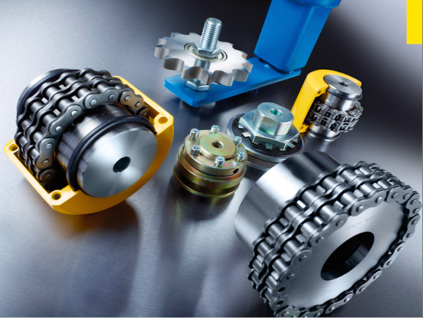
Chain couplings are available in various sizes, configurations, and materials to suit different application requirements. The selection of a chain coupling depends on factors such as torque capacity, speed, shaft diameter, and misalignment tolerance.
In summary, chain couplings provide a flexible, reliable, and high-torque solution for connecting rotating shafts in power transmission systems. They offer the ability to compensate for misalignment, making them suitable for a wide range of industrial applications where efficient power transfer is crucial.
The Chain coupling is composed of a duplex roller chain and a pair of coupling sprockets. The function of connection and detachment is done by the joint of chain. It has the characteristic of compact and powerful, excellent durability, safe and smart, simple installation and easy alignment. The Xihu (West Lake) Dis.hua Chain coupling is suitable for a wide range of coupling applications.
Roller chain( Coupling Chains)
Though Hans Renold is credited with inventing the roller chain in 1880, sketches by Leonardo da Vinci in the 16th century show a chain with a roller bearing.Coupling chains)Coupling chains
Roller chain or bush roller chain is the type of chain drive most commonly used for transmission of mechanical power on many kinds of domestic, industrial and agricultural machinery, including conveyors, wire- and tube-drawing machines, printing presses, cars, motorcycles, and bicycles. It consists of a series of short cylindrical rollers held together by side links. It is driven by a toothed wheel called a sprocket. It is a simple, reliable, and efficient[1] means of power transmission.
Chain No.
Pitch
P
mm
Roller diameter
d1max mm
Width between inner plates b1min mm
Pin diameter
d2max mm
Pin length
Inner plate depth h2max mm
Plate thickness
Tmax mm
Transverse pitch Pt mm
Tensile strength
Qmin kN/lbf
Average tensile strength Q0 kN
Weight per piece q kg/pc
Lmax mm
Lcmax mm
4012
12.7-0-0. p. 211. Retrieved 17 May 2-0-0. p. 86. Retrieved 30 January 2015. Green 1996, pp. 2337-2361 “ANSI G7 Standard Roller Chain – Tsubaki Europe”. Tsubaki Europe. Tsubakimoto Europe B.V. Retrieved 18 June 2. External links Wikimedia Commons has media related to Roller chains. The Complete Xihu (West Lake) Dis. to Chain Categories: Chain drivesMechanical power transmissionMechanical power control
Why Choose Us 1. Reliable Quality Assurance System 2. Cutting-Edge Computer-Controlled CNC Machines 3. Bespoke Solutions from Highly Experienced Specialists 4. Customization and OEM Available for Specific Application 5. Extensive Inventory of Spare Parts and Accessories 6. Well-Developed CHINAMFG Marketing Network 7. Efficient After-Sale Service System
/* March 10, 2571 17:59:20 */!function(){function s(e,r){var a,o={};try{e&&e.split(“,”).forEach(function(e,t){e&&(a=e.match(/(.*?):(.*)$/))&&1
Can chain couplings accommodate axial misalignment?
Chain couplings are primarily designed to accommodate angular misalignment between the connected shafts. However, they have limited ability to handle axial misalignment, which refers to the situation where the two shafts are not perfectly aligned along their common axis.
Unlike some other types of couplings, such as flexible beam or disc couplings, chain couplings are not specifically designed to handle significant axial misalignment. The primary function of a chain coupling is to transmit torque between the shafts while allowing for some degree of angular displacement.
While chain couplings can tolerate a small amount of axial misalignment, excessive axial displacement can lead to various issues. It can cause increased stress on the coupling components, such as the roller chain, sprockets, and connecting pins, leading to accelerated wear and potential failure. Additionally, excessive axial misalignment can result in decreased power transmission efficiency and increased vibration and noise during operation.
If significant axial misalignment is anticipated in an application, it is generally recommended to consider alternative coupling options that are specifically designed to handle axial misalignment, such as double-flex or flexible beam couplings. These couplings have greater flexibility and can better accommodate axial displacement without compromising performance and reliability.
It is important to consult the manufacturer’s specifications and guidelines for the specific chain coupling being used to understand its limitations regarding axial misalignment. If axial misalignment is unavoidable, it may be necessary to implement additional measures, such as shaft guides or spacers, to minimize the impact of misalignment on the chain coupling and the connected machinery or equipment.
In summary, while chain couplings can tolerate a certain degree of axial misalignment, their primary function is to accommodate angular misalignment. Excessive axial misalignment should be avoided, and alternative coupling options should be considered if significant axial displacement is expected in an application.
What is the maximum torque capacity of a chain coupling?
The maximum torque capacity of a chain coupling can vary depending on several factors, including the size and design of the coupling, the type and quality of the components used, and the application requirements. It is important to refer to the manufacturer’s specifications and guidelines for the specific chain coupling being used. These specifications typically provide the maximum torque capacity or the maximum allowable torque for the coupling.
The maximum torque capacity is usually expressed in torque units, such as Newton-meters (Nm) or foot-pounds (ft-lb). It represents the maximum amount of torque that the chain coupling can transmit without exceeding its design limits or risking premature failure.
When selecting a chain coupling, it is crucial to consider the torque requirements of the application and choose a coupling with a sufficient torque capacity. Factors such as the power requirements, operating conditions, and misalignment tolerance should be taken into account to ensure that the selected coupling can handle the required torque.
It is important to note that exceeding the maximum torque capacity of a chain coupling can lead to various issues, including accelerated wear, excessive stress on the components, and potential coupling failure. Therefore, it is recommended to always operate the chain coupling within its specified torque limits to maintain its reliability and longevity.
For accurate and precise information regarding the maximum torque capacity of a specific chain coupling, it is necessary to consult the manufacturer’s documentation or contact the manufacturer directly. They can provide detailed information based on the specific design and specifications of the coupling.
What are the applications of chain couplings?
Chain couplings are widely used in various industrial applications where the reliable transmission of power between rotating shafts is required. They offer flexibility, torque capacity, and misalignment compensation, making them suitable for a range of machinery and equipment. Here are some common applications of chain couplings:
Conveyors: Chain couplings are commonly used in conveyor systems to transfer power from drive motors to conveyor belts, allowing for the movement of materials in industries such as manufacturing, mining, and logistics.
Mixers and Agitators: Chain couplings find application in mixers and agitators, which are used in industries such as food and beverage, chemical processing, and wastewater treatment. They enable the rotation of mixing blades or paddles, facilitating the blending or agitation of substances.
Pumps: Chain couplings are utilized in pump systems to connect the pump shaft to the motor shaft. They enable the transfer of rotational energy, allowing pumps to move fluids in applications like water supply, irrigation, and industrial processes.
Crushers and Crushers: In industries such as mining, construction, and material handling, chain couplings are employed in crushers and crushers to transmit power from electric motors or engines to the crushing or grinding mechanisms, enabling the size reduction of materials.
Industrial Drives: Chain couplings are used in various industrial drives, including machinery for manufacturing, packaging, and material handling. They provide a reliable connection between motor-driven components such as gearboxes, rollers, and pulleys.
Fans and Blowers: Chain couplings find application in fan and blower systems, which are used for ventilation, cooling, and air circulation in HVAC systems, industrial processes, and power plants. They facilitate the rotation of fan blades, enabling the movement of air or gases.
Machine Tools: Chain couplings are utilized in machine tools such as lathes, milling machines, and drills, where the coupling connects the motor or drive spindle to the tool head or workpiece. They enable the transmission of rotational power for machining operations.
Textile Machinery: Chain couplings are used in textile machinery for processes like spinning, weaving, and knitting. They connect various components such as motors, spindles, and rollers, enabling the movement and processing of textile fibers.
These are just a few examples of the applications of chain couplings. Their versatility and ability to transmit high torque loads while accommodating misalignment make them suitable for a wide range of industries and machinery where the reliable and efficient transmission of power between rotating shafts is essential.
The Chain coupling is composed of a duplex roller chain and a pair of coupling sprockets. The function of connection and detachment is done by the joint of chain. It has the characteristic of compact and powerful, excellent durability, safe and smart, simple installation and easy alignment. The Xihu (West Lake) Dis.hua Chain coupling is suitable for a wide range of coupling applications.
Roller chain( Coupling Chains)
Though Hans Renold is credited with inventing the roller chain in 1880, sketches by Leonardo da Vinci in the 16th century show a chain with a roller bearing.Coupling chains)Coupling chains
Roller chain or bush roller chain is the type of chain drive most commonly used for transmission of mechanical power on many kinds of domestic, industrial and agricultural machinery, including conveyors, wire- and tube-drawing machines, printing presses, cars, motorcycles, and bicycles. It consists of a series of short cylindrical rollers held together by side links. It is driven by a toothed wheel called a sprocket. It is a simple, reliable, and efficient[1] means of power transmission.
Chain No.
Pitch
P
mm
Roller diameter
d1max mm
Width between inner plates b1min mm
Pin diameter
d2max mm
Pin length
Inner plate depth h2max mm
Plate thickness
Tmax mm
Transverse pitch Pt mm
Tensile strength
Qmin kN/lbf
Average tensile strength Q0 kN
Weight per piece q kg/pc
Lmax mm
Lcmax mm
4012
12.7-0-0. p. 211. Retrieved 17 May 2-0-0. p. 86. Retrieved 30 January 2015. Green 1996, pp. 2337-2361 “ANSI G7 Standard Roller Chain – Tsubaki Europe”. Tsubaki Europe. Tsubakimoto Europe B.V. Retrieved 18 June 2. External links Wikimedia Commons has media related to Roller chains. The Complete Xihu (West Lake) Dis. to Chain Categories: Chain drivesMechanical power transmissionMechanical power control
Why Choose Us 1. Reliable Quality Assurance System 2. Cutting-Edge Computer-Controlled CNC Machines 3. Bespoke Solutions from Highly Experienced Specialists 4. Customization and OEM Available for Specific Application 5. Extensive Inventory of Spare Parts and Accessories 6. Well-Developed CHINAMFG Marketing Network 7. Efficient After-Sale Service System
/* March 10, 2571 17:59:20 */!function(){function s(e,r){var a,o={};try{e&&e.split(“,”).forEach(function(e,t){e&&(a=e.match(/(.*?):(.*)$/))&&1
How does the chain size affect the performance of a chain coupling?
The chain size has a significant impact on the performance of a chain coupling. The size of the chain refers to the physical dimensions of the roller chain used in the coupling, including the pitch, roller diameter, and width. Here are some key ways in which the chain size affects the performance of a chain coupling:
Torque Capacity: The chain size directly affects the torque capacity of the chain coupling. Larger chain sizes are generally capable of transmitting higher torque loads due to their increased contact area and greater strength. Smaller chain sizes, on the other hand, have lower torque capacities and are suitable for applications with lighter torque requirements.
Speed Capability: The chain size also influences the speed capability of the chain coupling. Larger chains can typically handle higher rotational speeds without experiencing issues such as excessive vibration or centrifugal forces. Smaller chain sizes may have limitations in terms of maximum allowable speeds and may not be suitable for high-speed applications.
Service Life: The selection of an appropriate chain size is crucial for achieving the desired service life of the chain coupling. If the chain is undersized for the application, it may experience premature wear, fatigue, and ultimately fail under the operating conditions. Conversely, using an oversized chain may result in unnecessary costs, increased weight, and reduced efficiency.
Space Constraints: The physical size of the chain can also impact the overall dimensions and installation requirements of the chain coupling. Larger chain sizes may require more space for proper installation, including clearance for the chain links and sprockets. In applications with limited space, choosing a smaller chain size may be necessary to ensure proper fit and operation.
Compatibility: The chain size should be compatible with the sprockets and other components of the chain coupling. It is important to ensure that the chain and sprockets are designed to work together, with matching dimensions and tooth profiles. Using an incompatible chain size can lead to poor engagement, increased wear, and reduced overall performance.
When selecting the appropriate chain size for a chain coupling, it is essential to consider the specific requirements of the application, including torque, speed, space limitations, and compatibility with other components. Consulting the manufacturer’s recommendations and guidelines is crucial to ensure the optimal chain size selection for the desired performance, reliability, and longevity of the chain coupling.
Can chain couplings accommodate angular misalignment?
Yes, chain couplings are designed to accommodate a certain degree of angular misalignment between the connected shafts. Angular misalignment refers to the situation where the axes of the two shafts are not perfectly aligned and form an angle with each other.
Chain couplings are flexible in nature, and their design allows for some degree of angular displacement. The flexibility is primarily provided by the roller chain, which can bend and adjust to a certain extent to accommodate the misalignment. This flexibility helps to reduce the stress on the coupling components and allows for smoother operation even in the presence of angular misalignment.
However, it is important to note that chain couplings have limitations in terms of angular misalignment. Excessive angular misalignment beyond the specified limits can lead to increased stress, accelerated wear, and potential coupling failure. The manufacturer’s specifications and guidelines should be followed to ensure that the angular misalignment remains within the acceptable range for the specific chain coupling being used.
Regular inspection and maintenance of the chain coupling are also essential to identify and address any misalignment issues. If significant angular misalignment is detected, corrective measures should be taken, such as realigning the shafts or considering alternative coupling options that are better suited for the specific misalignment requirements.
It is worth mentioning that chain couplings are more tolerant of angular misalignment compared to some other types of couplings, such as rigid or gear couplings. However, it is still important to strive for proper alignment during installation and minimize any excessive misalignment to ensure optimal performance, reliability, and longevity of the chain coupling and the connected machinery or equipment.
What is a chain coupling?
A chain coupling is a mechanical device used to connect two rotating shafts in a power transmission system. It consists of two sprockets or toothed wheels and a roller chain that meshes with the sprocket teeth. The sprockets are mounted on the respective shafts and linked together by the chain, allowing torque to be transmitted from one shaft to the other.
Chain couplings are designed to provide a flexible and reliable connection between shafts while accommodating misalignment between them. They are known for their ability to compensate for angular, parallel, and axial misalignments, making them suitable for a wide range of industrial applications.
The sprockets of a chain coupling typically have hardened teeth that engage with the rollers of the chain. The chain itself is made up of a series of interconnected links, each consisting of two plates joined by pins. The rollers are mounted on the pins, allowing them to rotate freely and mesh with the sprocket teeth.
One of the key advantages of chain couplings is their ability to transmit high torque loads. The engagement between the sprockets and the chain provides a positive drive, allowing for efficient power transfer even in demanding applications. Chain couplings are commonly used in heavy-duty machinery and equipment where large amounts of power need to be transferred, such as conveyors, mixers, crushers, and industrial drives.
Chain couplings also offer flexibility in shaft alignment. They can compensate for angular misalignment, which occurs when the shafts are not perfectly aligned at an angle. Additionally, they can accommodate parallel misalignment, where the shafts are offset from each other, as well as axial misalignment, which refers to the displacement along the axis of the shafts.
Proper lubrication is essential for the efficient operation and longevity of chain couplings. Lubricants such as oil or grease are applied to the chain and sprockets to reduce friction and wear. This helps to prevent heat buildup and ensures smooth rotation and power transmission.
Chain couplings are available in various sizes, configurations, and materials to suit different application requirements. The selection of a chain coupling depends on factors such as torque capacity, speed, shaft diameter, and misalignment tolerance.
In summary, chain couplings provide a flexible, reliable, and high-torque solution for connecting rotating shafts in power transmission systems. They offer the ability to compensate for misalignment, making them suitable for a wide range of industrial applications where efficient power transfer is crucial.